0120-4558247
info@sugslloyds.com
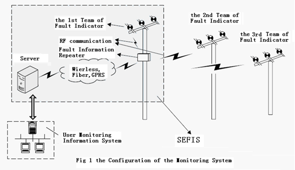
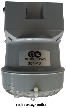
The Fault Passage Indicator is an automatic device for installation in overhead distribution lines, to monitor the current and voltage parameters in order to detect faults, and reduce outage time where it is installed. The indicator can be mounted under live conditions with the help of an adapter and a hot stick. The indication is done by six flashing LEDs. LEDs are placed in a concentrated vertebral body for better visibility. Fault message is sent to the Control Centre which sends message to the service team. Permanent andtemporary faults can distinguished and indicated separately. The FPI can be adapted to auto-reclosers in the network. This makes an optimized fault indication possible and also allows the indication of different fault types.It can measure the true virtual value of Current with a 12 bit ADC. Due to the bidirectional connection between the RF module and Fault Passage Indicator the real time current can be sent out any time, and the trip current setting and reset time can be set remotely without dismounting the FPI. Operational mode of FPI can be checked with the help of a magnetic switch. Additionally FPI can be reset using the switch. The data collection unit can save upto 100 local events in its memory.
Real time on line monitoring of fault information. Delay in data upload is less than a minute ( depending on the public network delay)
FPI battery under voltage, DCU battery failure, equipment failure or other equipment fault information. The alarm information gets timely recorded. Sound and light annunciation can be provided
Radio & GSM/ GPRS
System Configuration, alarm informations are stored in data base which facilitates statistics, analysis and inquiry
The normal white window turns red when short circuit of ground fault occurs, and information is sent to the manager and control station.
Does not get disturbed by inrush current, high harmonics, current fluctuation and cable capacitor bypass.
After the fault is attended and power is restored, fault indicator will reset automatically. Reset time can be selected by the customer based on the line environment, line inspection length and department requirements.
FPI- Monitor Shell is made of ABS material, poured and sealed with epoxy resin. DCU- Life> 10years
FPI- Clip-on type, easy installation and removal with the help of hot stick. Does not affect the running line.
DCU- Installed on pole with mounting bracket and hoop.
OS- Windows, CS architecture, Data Structure- SQL Server 2000 and above version
Real time on line monitoring of fault information. Delay in data upload is less than a minute (depending on the public network delay)
The normal white window turns red when short circuit of ground fault occurs, and information is sent to the manager and control station.
Does not get disturbed by inrush current, high harmonics, current fluctuation and cable capacitor bypass.
After the fault is attended and power is restored, fault indicator will reset automatically. Reset time can be selected by the customer based on the line environment, line inspection length and department requirements.
FPI- Monitor Shell is made of ABS material, poured and sealed with epoxy resin. DCU- Life> 10years
FPI- Clip-on type, easy installation and removal with the help of hot stick. Does not affect the running line.
DCU- Installed on pole with mounting bracket and hoop.
1. Indication of Short Fault Alarm: The short sensors measure short fault current,when a short fault occurred, the current measured by the sensors exceeded the setting current, then the sensors would send the signals to the mainframevia the optical fibers, the mainframe would give the relatively alarm information.
2. Indication of Earth Fault Alarm: The earth fault sensor measures zero sequence current, when a earth fault occurred, the current measured by the sensor exceeded the setting current, the sensor would send the single to the mainframe viathe opticalfiber, the mainframe would give the relatively alarm information.
3. Low-Voltage Alarm: The mainframeis battery-powered. When the battery voltage is lower than normal voltage, there is an alarm to remind operatorto change the battery.
4. Automatic Reset: When the indicator gave alarms, it can reset itself after a setting time if there is no manually reset.
5. Manually reset: When the indicator gave alarms, if the “reset/test”button on thepanel is pushed and kept for 2sec, the alarm would be cleared up.
6. Automatic: When the indicator gave alarms, it wouldsend out remote single via relays, and also, it can receive remote signal to reset itself.
7. Test: The indicator can be checked by itself.